The problem
My beamforming ground station needs four antennas, and a phased array is fussy about them in a way a single antenna never is. The four elements have to be electrically identical, because any difference between them shows up as a phase or amplitude error I didn’t ask for. And each one’s phase centre has to sit exactly where the maths says it is. At 915 MHz, being 10 mm off is about 11° of phase error before the phase shifters have done anything.
Off-the-shelf 915 MHz antennas don’t tell you where their phase centre is, or promise it’s the same from one unit to the next. Hand-built brass ones can’t promise it either.
Constraints
- Four elements that match each other, not just one good one.
- Detachable, so each one connects through an SMA connector.
- No full-wave EM simulation. That was outside the project’s scope, so the dimensions came from closed-form estimates.
- Reproducible: anyone should be able to order identical replacements from the same files.
How it works
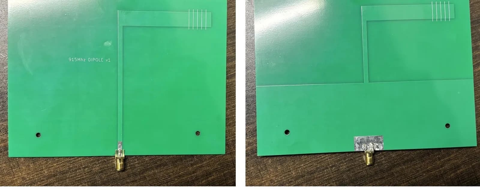
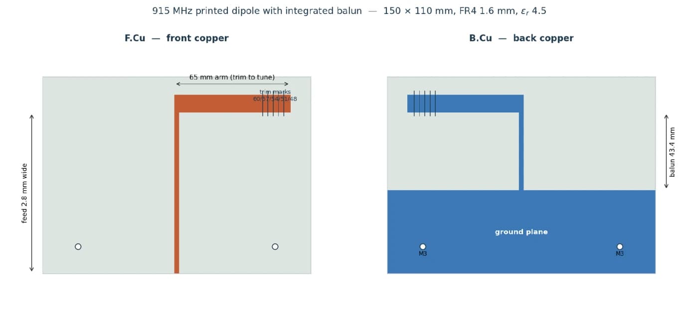
The dipole is printed on the PCB, and so is the balun that feeds it. A 50 Ω microstrip line (2.80 mm wide on 1.6 mm FR4) carries the signal up from the SMA connector. Part way up the board, the ground plane underneath stops and narrows into a strip the same width as the trace. That makes a parallel-strip line, which is balanced, and over its 43.4 mm quarter-wave length the unbalanced current turns into balanced current. At the top, each strip opens into one arm of the dipole on its own side of the board.
The balun section works out to about 63 Ω, between the 50 Ω feed and a printed dipole’s usual 65 to 75 Ω, so it also does some impedance matching for free. I didn’t design for that; it just fell out of the geometry.
I drew the copper directly in KiCad’s PCB editor (an antenna has no netlist, so there’s no schematic), got it DRC-clean, and ordered five boards: four for the array and one spare.
The hard part
Every version fought me on the balun, the bit that stops current running down the outside of the feed cable. In an array that matters more than usual: stray radiation from the cable would change every time the cables moved, and I’d end up measuring my cable routing instead of the beamforming.
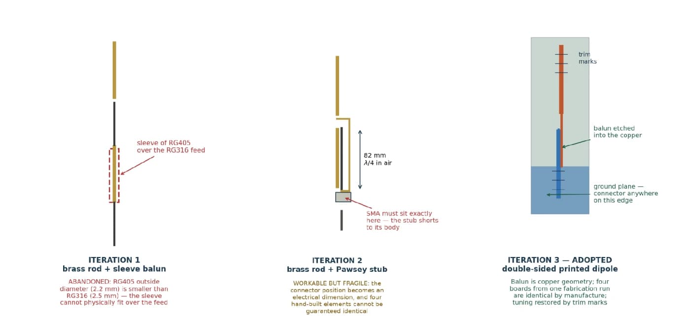
- Brass rod with a sleeve balun. The plan was to slide RG405 semi-rigid over the RG316 feed. RG405 is about 2.2 mm across. RG316 is 2.5 mm. That plan died on paper.
- Brass rod with a Pawsey stub. This one worked electrically. But because the elements had to be detachable, the stub shorted to the SMA connector’s body 82 mm below the feed, so the connector’s position became an electrical dimension I had to reproduce to the millimetre, four times, by hand.
- Printed dipole. Four boards from one fab run match to about 0.1 mm, with no stubs to cut or solder.
The arm length was the other unknown. My two closed-form estimates said 49 mm and 58 mm, which disagree by almost 20 %. So I had the arms fabricated long, at 65 mm, with silkscreen trim marks at 60, 57, 54, 51 and 48 mm. Too long is fixable with a blade; too short is not.
Then the boards came back resonating at 901.6 to 904.6 MHz, already well matched at 915 MHz. Trimming to the first mark would have pushed resonance to around 977 MHz, so I didn’t trim anything. The real resonant arm length is close to 64 mm, meaning both estimates were short (by 23 % and 9 %) because neither accounts for the 10 mm arm width or the balun.
Measuring them came with its own lesson: standing next to the array while it was being swept moved the resonance by about 10 MHz, so every recorded sweep was taken with me standing well clear.